Attempting a 0dBm reference
0dBm
Attempting a 0dBm reference
Warning: This is my lab notebook, there are some bad turns and mistakes along the way, but I think I sort it out in the end.
Motivation
I have plans (and have built the analog part) for an RF power meter of the AD8307 type. This needs to be calibrated. For the initial tests, I was quite happy that I got reasonable results interpreting the output from my HP8657a RF signal generator. When it was new and calibrated, it promised ±1 dB level accuracy (typically ±0.5 dB), but it is old, and for small power levels my scope cannot provide good measurements.
So it would be perfect to have a reference that could be used to calibrate my power meter—perhaps in conjunction with some Mini-Circuits attenuators that I have and trust.
Design and build
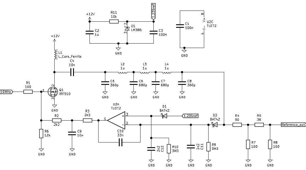
I came across a circuit online which seems to promise a no-tune calibrator. It is known as the DL7AV calibrator, and Hans Summers built one in a YouTube video. I attempted a modification to 10 MHz; this is the version that I originally built (mistakes and all).
The plan is that Q1 will not amplify unless there is positive bias at the gate, and this is controlled by the op-amp. Following Q1, there is a low-pass filter (calculated using the rf-tools calculator). The filter is necessary to guarantee a fairly pure tone, since we will be calibrating power based on voltage peak-to-peak readings.
This is rectified, and the op-amp compares the peak of this filtered signal with the 5 V reference (U1). If the rectified signal is smaller than 5 V, U2 increases the bias at Q1’s gate, until there is 5 V before the attenuator. The control-loop should be low impedance, so I add a 50 ohm resistor.
5 V peak into 50 ohms is:
\[ (5V/\sqrt{2})^2/50\Omega = 0.25W = 10\log_{10}(250mW/1mW)\,\mathrm{dBm} = 23.97\,\mathrm{dBm}. \]
The schematic shows exact values for a 23.97 dB attenuator, but commercial values (390 and 56 ohm) are close enough at 24.1 dB.
There are some assumptions about the op-amp not loading down the rectified RF (so that we measure true peaks). The original circuit used a LF356. The TL072 is definitely not rail-to-rail (but I bought a lot of these on eBay a while back). I did not plan on battery operation, so I used a 12 V supply.
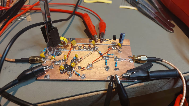
This is what the first build looked like:
First power-up experience
The experience was: too much current; the supply drooped to just over 7.1 V at 100 mA. At that point, the rectified DC at the op-amp was short of the voltage reference, the op-amp output was probably around 5.5 V, and bias at the Q1 gate was 4.24 V.
However, I was measuring about 200 mV rms on the output (terminated with 50 ohm), which is in the neighborhood of the 225 mV of 0 dBm. The circuit was burning hot, in a bias-restricted equilibrium.
After some fiddling with parts, looking for short circuits, and replacing the RF choke (25 turns on FT50-43), things improved slightly. The point of this choke is to provide a high resistance to RF, such that RF would rather enter the low-pass filter than the power supply.
For input signal, I tried both my Colpitts oscillator from a previous post, but settled on something similar to what Hans Summers used: a 5 V square wave from my Rigol function generator.
Trying to figure out what was wrong, I connected the second channel of my PSU to the midpoint of R2 and R3 and adjusted until I had 223 mV at the output. I found that I could reach this with a bias at 3.867 V, at which point the current from the supply was about 55 mA. So a higher bias eventually led to less output.
Trying to fix the unstable bias
That a higher bias eventually leads to lower output is perhaps not so strange: with sufficiently high bias, the signal is not able to modulate the drain, because Q1 is always on.
The question is what the op-amp will do on startup. At first there is no bias, so no RF to be rectified, and the op-amp will try to drive the gate hard. If it drives the gate too hard, it will get past the unstable high-bias equilibrium and go into current limitation.
One possibility is to restrict the initial bias by installing a large electrolytic capacitor to ground between R2 and R3. I tried a 220 µF capacitor. It slows down the turn-on, but it eventually reaches the same level.
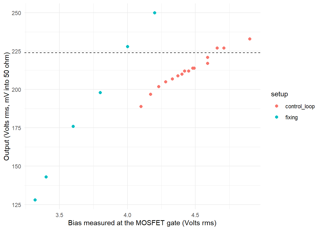
More measurement
The dashed line represents the target of 224 mV (rms) into 50 ohm, i.e. 0 dBm.
Attenuation
I have a pi attenuator with 50 ohm in and out. Following the EMIRFD formulas:
RP <- function(R, V) R * (1 + V) / (1 - V)
RS <- function(R, V) 2 * R^2 * RP(R, V) / (RP(R, V)^2 - R^2)

RP(50, sqrt(0.1) / 5)
[1] 56.75156RS(50, sqrt(0.1) / 5)[1] 393.7036Conclusion
So a bit off, but taking into account tolerances, being less than a dB off is not so bad. Some trimming in the final build should be able to sort that out.